This is the first in a series of three companion blog posts about dependency graphs. These blog posts explore the key terminology, graph theory concepts, and the challenges of managing large graphs and their underlying complexity.
- Introduction to the dependency graph
- Managing dependency graph in a large codebase
- The anatomy of a dependency graph
A dependency graph is a representation of how different parts of a software project rely on each other. Understanding the dependency graph helps a software engineer see the bigger picture of how their component fits into the whole project and why certain changes might affect other areas. It’s a useful tool for organizing, debugging, and improving the source code.
Engineers responsible for managing the development and build environments also benefit greatly from understanding dependency graph concepts and how they are used by the build system. This knowledge is crucial for optimizing build times since it allows engineers to identify opportunities to parallelize and improve the incrementality of builds. Understanding the dependency graph also helps in troubleshooting build failures, managing changes safely, and ensuring that updates or refactors do not worsen the overall design of the codebase.
In this blog post, we’ll take a fresh look at dependency graphs, starting from the basic concepts and building up from there. You will learn what a dependency graph is, some terminology required to be successful in managing it, and what it is used for.
What is a dependency graph?
A dependency graph is a visual map that explains the connectivity between parts of a software project.
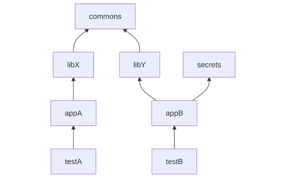
Let’s use a contrived example of a dependency graph in a tiny codebase and lay out some key terminology.
Nodes and edges
A node in a dependency graph represents an individual item which can be a software package, a module, or a component.
The edges (connections) between nodes represent dependencies, meaning one node relies on another to function or build correctly.
Dependencies
appA depends on libX directly therefore libX is a direct dependency of appA.
For example, if you import the requests package in your Python module,
this would be that module’s direct dependency.
appB depends on commons via libY therefore commons is a transitive dependency of appB.
For example, if your C++ program depends on libcurl, then it also depends (transitively)
on every external library that libcurl depends on
such as OpenSSL or zlib.
Dependents
libX and libY directly depend on commons.
This could also be reversed — commons has two direct dependents: libX and libY.
In fact, the dependents are often called reverse dependencies.
Similarly, secrets have two reverse dependencies: one direct - appB, and one transitive - testB.
Shape and orientation
A simple dependency graph can sometimes look like a tree, with one common base component at the root, supporting multiple dependents (components pointing back towards the root), which in turn are depended on by the leaves (components with no further dependents).
However, dependency graphs are usually more complex than trees and belong to a more general family of graphs known as directed acyclic graphs (DAG), where you can only follow the arrows in one direction, and you can never end up back at the same node you started from. We’ll talk about the word “acyclic” in more detail later in the post.
When describing this project, we could emphasize that commons is foundational -
the root that everything else builds upon.
Libraries and apps become the trunk and branches, with tests as leaves.
Without clearly defining how arrows show dependencies,
we might easily draw all arrows pointing the opposite way (a reverse dependency graph1):

This makes terms like “roots” or “leaves” potentially confusing, but it’s important to be aware of them as you will likely hear them being used when talking about graphs.
What is it used for?
Dependency graph concepts have lots of applications:
-
Dependency resolution techniques such as Minimal Version Selection and Backtracking are used by package managers.
-
In artifact-based build systems such as Bazel, a dependency graph is used to determine the order in which different parts of a project should be built. Having access to this allows building only what is necessary and in the correct sequence.
-
GNU Make uses a dependency graph implicitly through its rules: each target specifies its dependencies, and Make constructs a graph to determine the order in which to build targets.
-
Native programming language build tools use the dependency graph to fetch and build modules in the correct order, e.g., in Go, it is used to maintain a cache of passing test results (where
go testchecks whether any of the transitive dependencies of the tests have changed since the last run).
Graph theory applications
Graph theory is a branch of mathematics focused on networks of connected items. Understanding some graph theory ideas can make managing dependencies much smarter. Being familiar with the terminology also helps to find relevant tooling, for instance, knowing that part of the graph is called subgraph would let you find more relevant results when searching for algorithms to extract a part of the graph.
Connected Components
A connected component is a group of nodes where each one can reach every other by following edges in either direction. In a dependency graph, this means a set of source code modules that are all linked together by a dependency link (or a reverse dependency link) — what’s important is that there is some sort of connection.
When two applications share modules in the same connected component, they become indirectly connected which might make it hard to test or deploy them separately. In a worse scenario, if the modules of these apps actually import from each other, then code changes in one app can unexpectedly break another. Applications with isolated dependencies are much easier to extract and move to separate repositories.
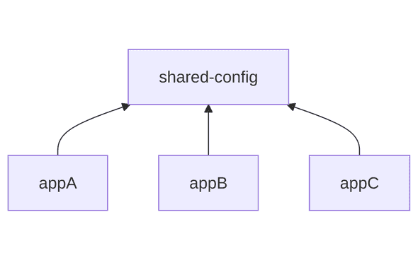
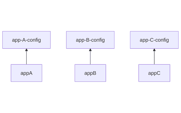
In the example below, the configuration is shared among three applications making them part of the same connected component. That is, you can’t move any of the applications along with the shared configuration out of the codebase. This could be refactored by splitting the shared configuration into separate configurations for each application.
Making changes specific to the appA in the shared-config no longer triggers rebuilds of all applications
and running all their tests.
One connected component:
Three connected components:
Isolated nodes (nodes that don’t have any edges connected) also are connected components which may represent software units that are no longer needed. For instance, a program might have once used a third-party library, but later stopped using its functionality. If nothing else in the codebase depends on that library, it is now isolated, and can be removed to avoid rebuilding.
Cut Points and Bridges
A cut point (also called a “point of connection” or “articulation point”) is a node that, if removed, would split the graph into separate components. A bridge is an edge whose removal would produce a new connected component.
In the example below, if we stop depending on the third-party library third-party-lib,
we would stop depending transitively on all those third-party libraries
that third-party-lib brought into the dependency graph of our project.
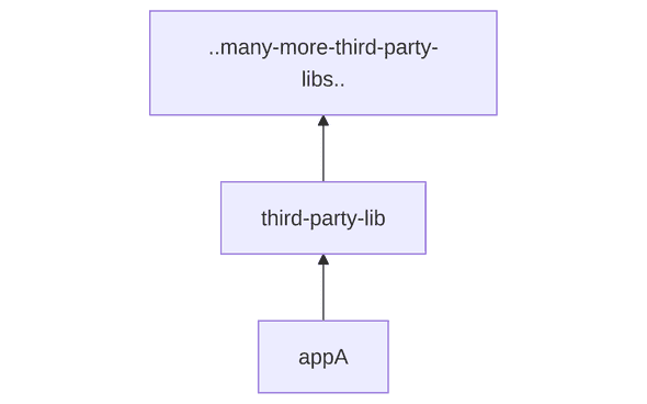
To remove a “cut point” like third-party-lib, you can replace its functionality with an existing dependency or reimplement it yourself.
This can make builds faster (fewer downloads), more secure, and more reliable.
The npm left-pad incident shows
how third-party dependencies can cause problems.
Creating isolated groups in the dependency graph is often a good thing as it means those modules can now evolve, be tested, and deployed independently, reducing risk and complexity. However, in a large dependency graph, the hard part is to identify the best cut points as often breaking the dependency between two modules might still leave the part of the dependency graph you are concerned about connected to the rest of the codebase.
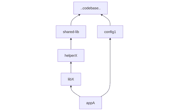
Breaking appA -> config1 (incorrectly assuming that this as a bridge)
would still leave appA connected to the rest of the codebase via the libX connection.
To identify that libX might still lead to the rest of the codebase via a chain of connections is not trivial
and to be able to refactor the dependency graph so that one can reason about it,
it is often required to use advanced dependency graph querying and visualization tooling.
To estimate how much work it would be to break a connection, one can list all paths between your module
and the undesired dependency, which will be discussed later.
Subgraphs
A subgraph is just a smaller part of the whole graph, focusing on a subset of nodes and their connections. Depending on the complexity and shape of your dependency graph, it might only make sense to interact with a subgraph of it. Take a look at the dependency graphs of the microservices at tech giants to appreciate the complexity of their dependency management.
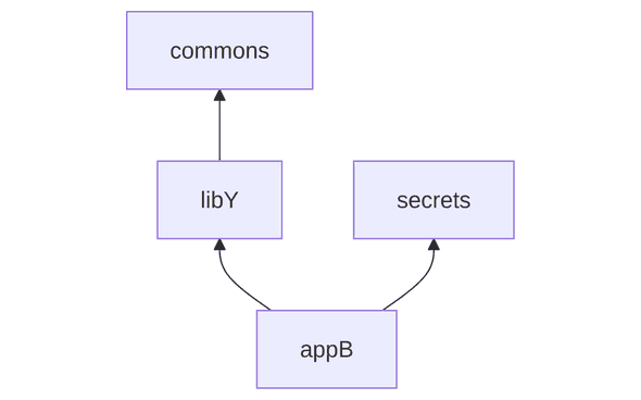
Visualizing or analyzing a subgraph (e.g., all dependencies of a single service) helps you zoom in on what matters for your project. If the dependencies of a program are complicated, it may make sense to extract only its direct dependencies and their direct dependencies. In graph theory terms, this means focusing on nodes that are at most two degrees away from the program node. The degree of a node refers to the number of direct connections (dependencies) it has. We can extract a subgraph by limiting our view to nodes within a certain depth (in this case, a depth of two). By controlling the depth, you avoid being overwhelmed by the entire transitive chain of dependencies.
With the same dependency graph we had seen in the very first graph of the post,

we can extract the subgraph containing dependencies with depth of 2 for appB:
Transitivity
The transitive closure of a node in a graph is the set of all nodes that can be reached from that node by following edges. In the context of a dependency graph, the transitive closure2 of a module is the entire “tree” of things required for that module to work.
In this dependency graph,
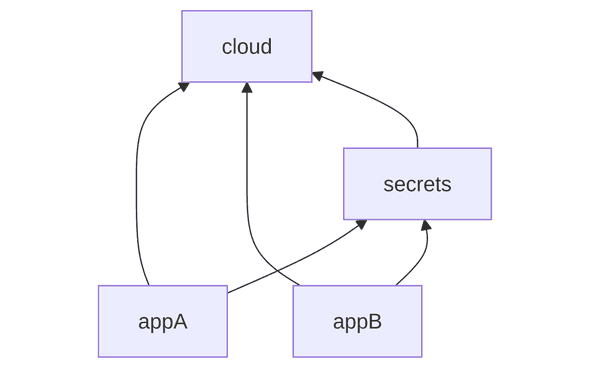
both appA and appB depend on secrets (directly) and cloud (directly and transitively).
In this cluttered visualization of the graph, the direct dependency edge between appA/appB and cloud
could be removed for clarity as we already know that they are connected:
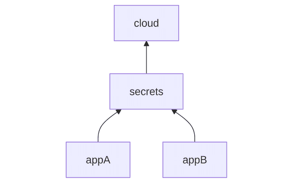
The process of simplifying the graph by removing edges that are implied by other edges is called transitive reduction. Keep in mind that you would not normally want to do this for any other reason than clearer visualization of the graph.
If your build tool tracks node dependencies by reading build metadata (stored in files maintained by engineers),
this information must stay up-to-date so the build system can correctly identify necessary build steps.
Imagine that at some point in time appA used to import some code from cloud, however, after some refactoring,
it doesn’t depend on it directly any longer:
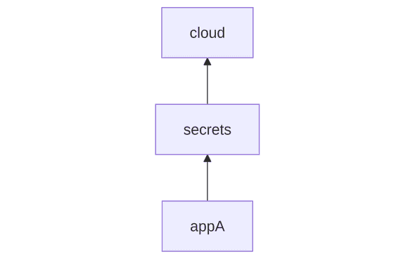
Now, what if in the build metadata files, the direct dependencies of appA are still [cloud, secrets]?
The stale build metadata information such as a redundant declaration of the direct dependency won’t be an issue
from the build systems perspective: cloud will ultimately end up in the transitive closure of appA.
However, if after further refactorings, appA no longer depends on secrets, we end up with this graph used by the build system:
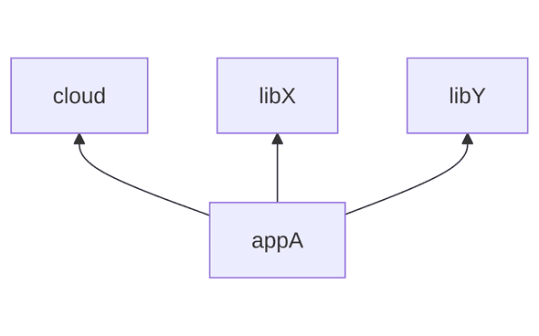
Since appA depends on cloud, it becomes dependent on the transitive closure of cloud
which might lead to slower build times (all resources that cloud depends on now need to be downloaded to build appA).
Paths
Finding paths between arbitrary modules in a dependency graph helps understand how different parts of your system are connected. In this context, we are primarily interested in finding simple paths — paths where all nodes visited are distinct.
By finding a path from module A to module B, you can see if changes in A might affect B (or vice versa). This helps estimate the risk of changes and debug issues that propagate through dependencies. For example, if a module contains source code under a specific license, you might want to ensure no paths from applications with incompatible licenses lead to it, preventing its inclusion in the application bundle.
With this contrived example of a dependency graph,
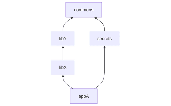
there are two paths from appA to commons:
appA->libX->libY->commonsappA->secrets->commons
In a large, highly connected dependency graph, there may be hundreds of paths between two modules.
When listing paths, shortest paths help to understand the minimal set of dependencies connecting two modules. In contrast, the longest path between two modules tells you how deep the dependency chains are. The higher the average number of nodes in all paths in the graph, the more interconnected your codebase is. Having a very interconnected dependency graph might be problematic because it becomes hard to reason about how changes will propagate and a change in a low-level module can ripple through many layers, increasing the risk of unexpected breakages.
Topological sort
Topological sort (or order) is a way of ordering the nodes in a dependency graph so that every node comes after all the nodes it depends on. A build system might use topological sort to determine what must be built first and which targets can be built in parallel.
Having access to this contrived dependency graph,
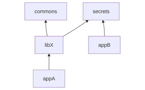
and oversimplifying what a modern build system would do with this dependency graph, we could produce a parallelizable list of build actions.
In order to build a particular node (say, produce a binary executable), we need to first build all nodes
that this node depends on (transitively).
For instance, let’s say we want to build appA:
- To build
appA, we need to first build its direct dependency,libX. - To build
libX, we need to first build its direct dependencies,commonsandsecrets. commonsandsecretscan be built immediately as they do not have any dependencies.
This means that our dependency graph nodes would be sorted like this:
[secrets,commons],libX,appAsecrets and commons can be built in parallel, and once both of them are built,
we can start building libX, and, thereafter, appA.
Parallelism emerges only when the graph has branches, that is, multiple independent subgraphs that can be built concurrently once their dependencies are satisfied. Practically, this means that flattening overly nested or serial dependencies can unlock better parallelism leading to faster builds.
In an extreme case, if your graph is in the shape of a linked list
such as app -> lib -> secrets -> commons, no parallelism can be achieved
because every node would need to wait for its dependency to be built first.
However, even when components must be built sequentially due to their dependencies,
parallelism can still occur within each component,
for instance, compiling multiple source files simultaneously within a single library.
Cycles
Cycles in a dependency graph mean that some components depend on each other in a loop, making it impossible to determine the order in the dependency chain. Build systems like Bazel require the dependency graph to be a directed graph without cycles (commonly known as Directed Acyclic Graph, or DAG) because cycles would lead to infinite build loops and prevent the system from knowing which component to build first.
With this graph having a cycle (libA -> libB -> libC), it is unclear
in what order dependencies of app should be built:
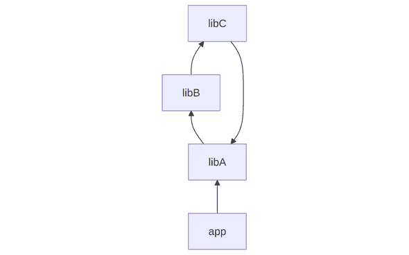
When adopting a build system that needs to construct a DAG out of your dependency graph, you might need to make refactorings in the codebase to break cycles. This is particularly true for legacy codebases written in Python, JavaScript, or Ruby where native build tools might tolerate cycles in the dependency graph.
A DAG is a very common data structure used by various build systems such as Bazel, Pants, and Buck2, process orchestration software such as Dagster, Flyte, and AirFlow, and software engineering tooling such as Git.
In this post, we have reviewed the basic principles related to graph theory and talked about dependency graphs that consist of modules in a codebase. In sophisticated build systems, you’ll find that more kinds of graphs exist, with differences between them. In Bazel, there is a build graph (what we have called dependency graph in this post for simplicity) and an action graph that breaks down each component into specific actions (like compiling a file or generating code) that need to be executed. There are some more advanced kinds of graphs you might run into such as the evaluation graph (Skyframe graph) representing Bazel’s internal state (see skyscope to learn more) and the shadow dependency graph which is created when aspects are used.
In the next blog post, we will cover common problems associated with managing project dependencies and share best practices for keeping a large dependency graph healthy over time.
- The reversed dependency graph concept is useful in scenarios like impact analysis (e.g., “If changes are made to this core library, what other components will be affected?”).↩
- You won’t see this term often, but the transitive closure that also includes the node itself from which we start the search is called a reflexive transitive closure.↩
Behind the scenes
Alexey is a build systems software engineer who cares about code quality, engineering productivity, and developer experience.
If you enjoyed this article, you might be interested in joining the Tweag team.